
Power over Ethernet (PoE) technology simplifies enterprise and datacenter building infrastructure, enabling power delivery over network cables to provide data connectivity and power supply with a single cable.
The convenience of PoE, however, comes at a cost. When designing structured telecommunications cabling systems for PoE, engineers must consider an additional factor that is not a concern for simple, network-only cable installations. When delivering power in any cable, a small portion of the power is dissipated as heat due to the DC resistance of the conductors. This heat causes a temperature rise in the cabling that can diminish cable life, degrade data transmission performance and even pose a fire risk. Heat dissipation rises with decreasing conductor diameter and temperature rise is amplified in installation scenarios that bundle multiple cables together. Consequently, designers must account for these factors during the design of PoE cabling systems to properly manage temperature rise and keep cables below their maximum operating temperature.
Thinner 28 AWG and 26 AWG stranded Ethernet patch cord cables offer flexibility, easier cable management and improved air flow around server racks compared to thicker network cables. However, they also dissipate more power as heat, requiring a focus on installation configuration (e.g., bundle sizes) to maintain desired performance levels and safe operating conditions.
PoE types
PoE dates back to 2003, when IEEE approved the 802.3af standard. Proprietary methods to deliver power over network cables existed before 802.3af, but the new standard defined a systematic way to supply power from power sourcing equipment (PSE) over an Ethernet cable to a powered device (PD). 802.3af allowed power delivery over two of the four pairs of conductors in an Ethernet cable, with a maximum power output from the PSE of 15.4 W, ensuring a minimum of 12.95 W delivered to the PD. This level of PoE is known as Type 1.
Power demands multiplied as PoE grew in popularity due to its convenience and as more varied devices with increasing capabilities were deployed. In 2009, IEEE ratified the 802.3at standard that defines Type 2 PoE and increases the amount of power supplied over two energized pairs to a maximum 30 W from the PSE, and a minimum power delivery to the PD of 25.5 W.
The latest PoE standard, IEEE 802.3bt, defines two additional PoE types, Type 3 and Type 4, each utilizing the full four pairs of the cable to deliver power alongside data. Type 3 PoE allows a maximum power output from the PSE of 60 W and a minimum power delivery to the PD of 51 W. Type 4 PoE permits up to 99.9 W for the PSE and PD power delivery of 71 W. Note Type 4 complies with the 100 W per port limit imposed by the limited power source and safety extra low voltage (SELV) requirements defined in ISO/IEC 60950.
| Standard | IEEE 802.3af | IEEE 802.3at | IEEE 802.3bt | |
| Common Terminology | PoE | PoE+ | PoE++/4PPoE | |
| PoE Type | 1 | 2 | 3 | 4 |
| Date of Standard Ratification |
2003 | 2009 | September 2018 | |
| Maximum Number of Energized Pairs |
2 | 2 | 4 | 4 |
| Maximum DC Current per Pair |
350 mA | 600 mA | 600 mA | 960 mA |
| Maximum Power Delivered by the Power Sourcing Equipment (PSE) |
15.4 W | 30 W | 60 W | 99.9 W |
| Minimum Required Power at the Powered Device (PD) |
12.95 W | 25.5 W | 51 W | 71 W |
| Maximum Data Rate | 1000BASE-T | 1000BASE-T | 10GBASE-T | |
Stranded vs. solid conductors

Generally Ethernet cables are comprised of eight conductors arranged in four pairs, with each conductor in the pair twisted around its partner in a helical configuration. Each conductor is covered by an insulating material such as polyethylene or fluorinated ethylene propylene (FEP) to protect the metal wire from environmental exposure degradation and meet electrical performance. The four pairs are optionally wrapped in a shield such as aluminum polyester foil to minimize electromagnetic interference (EMI) and crosstalk. The assembled pairs are then enveloped in a protective outer jacket (e.g., polyvinylchloride) for protection from the environment.
Ethernet cables are supplied with two different types of core conductor configurations: stranded and solid. The conductors in stranded Ethernet cables are comprised of several smaller wires twisted together. Solid Ethernet cables, on the other hand, have a single wire for each conductor. Each of the various categories of Ethernet cable defined by ANSI/TIA-568 and ISO/IEC 11801, including category 5e, 6 and 6a, is available in either stranded or solid configurations.
Gauge size describes the thickness of each conductor and is commonly measured in American wire gauge (AWG). The number of strands per conductor is indicated by additional numbers after the conductor gauge size. For example, 28 AWG 7/36 indicates that the 28 AWG conductors in the cable are each comprised of seven wires with thicknesses of 36 AWG.
Stranded cables have a number of advantages compared to solid cables. They exhibit lower DC resistance, resulting in less heat generation for a given current passing through them. Their twisted, multi-wire construction also resists breakage when exposed to repetitive bending. Stranded cables’ durable flexibility makes them well-suited for applications like patch cabling, where installations may require sharp bends or frequent relocation.
Solid cables are more susceptible to damage from bending. They are better suited to permanent installation in applications like horizontal cabling and backbone cabling between entrance facilities, equipment rooms and telecommunications closets.
Design considerations for PoE 28 AWG and 26 AWG stranded patch cable

When selecting Ethernet cable gauge size, engineers should take into account a number of design considerations. 28 AWG and 26 AWG stranded patch cables have several advantages compared to thicker cables. With smaller diameters, they weigh less and occupy less space. This is particularly beneficial in cramped locations near patch panels, where dozens of cables converge in a small space. Smaller, lighter patch cables enable easier cable management and allow more air flow to reach network equipment.
Insertion loss
On the other hand, thin 28 AWG and 26 AWG Ethernet cables have higher insertion losses than cables of thicker gauges. Insertion losses are also higher for stranded cables than solid cables. Insertion loss, or attenuation, is the ratio of received signal power at the end of the cable to the signal power inserted at the start of the cable, measured in decibels (dB). It represents the amount of signal power lost over the length of the cable.
Insertion loss rises with increasing cable length, signal frequency and cable temperature. As a result, it is important to design cable systems with appropriate margins for insertion loss based on cable size, environmental operating conditions and signal characteristics. This involves derating, or shortening, the length of channels to ensure sufficient signal-to-noise ratio and avoid data packet loss. For example, the total length of a channel incorporating 28 AWG patch cord should be shortened to counteract the high insertion loss from thin, stranded conductors.
DC resistance
28 AWG and 26 AWG patch cables also have higher DC resistances compared to thicker-gauge cables. As a result, they generate more heat per unit of current that flows through them, resulting in higher cable temperatures for the same current capacity. The consequence of this high resistive heating is that thin cables safely carry less current than thick cables. If cable temperature rises above the rating of the cable’s insulation and jacketing, the cable could melt or catch fire.
Shielding
Shielding can help mitigate thermal risks. Cables with integral foil shielding wrapped around the conductors dissipate heat more efficiently than unshielded cables. The metal foil conducts heat away from the interior of the cable to its exterior surface, where radiation and convection convey heat away from the cable. Temperature rise is thus reduced for shielded cables, allowing them to safely carry high currents.
Quabbin Wire and Cable Co. offers 28 AWG and 26 AWG patch cords with a patented design that maximizes shield effectiveness and improves heat dissipation. The design eliminates both the spline and polyester tape inside of the cable that typically separates the conductor pairs to reduce crosstalk. Instead, a special shield arrangement achieves this same purpose. The lack of a spline eases patch cord assembly since there is no need to carefully cut it out during fabrication. The cable is also light and effectively dissipates heat.
PoE Standards and Installation Guidelines

Engineers designing cable systems with 28 AWG and 26 AWG stranded patch cables can refer to requirements and guidance provided by a number of standards, guidelines, certifications and codes.
The Telecommunication Industry Association’s (TIA) ANSI/TIA-568.2-D standard specifies mechanical and transmission requirements for balanced twisted-pair telecommunications cabling and components. In general, the standard requires 22 AWG to 28 AWG for cord cable, These include limiting the maximum length of 28 AWG cords in a channel to 15 m; derating the maximum channel length to make up for the high insertion loss of 28 AWG cord according to Annex G of the standard; and following the guidelines enumerated in Technical Systems Bulletin TIA-TSB-184-A-1.
TIA-TSB-184-A-1 provides conservative guidance for 28 AWG cord cables, specifying the temperature rise for various cable bundle sizes and different current levels. It also recommends the maximum number of cables allowed in a bundle to limit temperature rise to 15° C at ambient temperature conditions of both 20° C and 45° C. TIA-TSB-184-A-1 is an addendum to TIA-TSB-184-A, which provides similar guidance for 26 AWG stranded cord cables as well as thicker cable gauges.
The 2017 National Electric Code (NEC) 725.144 does not cover patch cable.
For generic cables the standards sets limits on bundle size, length and temperature rise based on minimally compliant cable. Quabbin performs tests and offers supporting data on each of our category cables to support PoE recommendations that exceed the standards limits.
CMR vs. CMP
The 2017 NEC also specifies cable rating requirements based on the spaces inside a building in which cables are installed in order to limit the spread of fire and smoke in the event of a fire emergency. Riser-rated cables (i.e., CMR) are rated for installation in risers (i.e., vertical shafts) between floors in a building through which wiring, conduit and pipes are routed to transfer power and utilities through a building. CMR cables must resist spreading fire from floor to floor. Plenum-rated cables (i.e., CMP) are rated for installation in building plenum spaces, which are areas for air circulation for heating and air conditioning. CMP cables have strict flame propagation as well as low-smoke requirements.
Quabbin PoE test capability
Determining the proper cable and installation configurations for 28 AWG and 26 AWG stranded patch cable PoE applications can be a complicated and lengthy process. Quabbin Wire and Cable Co. simplifies matters by providing customers with specific guidance relative to their unique application. This is enabled by Quabbin’s capability to evaluate temperature rise for most bundle sizes and current levels.
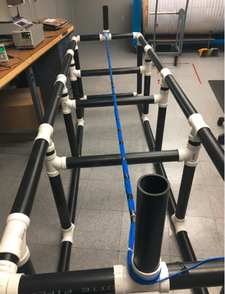
Quabbin’s test setup consists of a fixture holding a bundle of cables through which a constant DC current is delivered by a power supply. Ambient temperature is fixed at 20° C. Thermocouples connected to a data logger are placed inside slits in the center cable and outermost cable as well as on the fixture. Temperature rise at the center of the bundle is recorded for the duration of each test. Each test is run until the temperature has stabilized, a condition defined as a temperature variation of not more than 0.3° C in 15 minutes. The next test is not started until the bundle has returned to ambient temperature. The average duration of a test is 1 hour and 30 minutes. Tests are run for a variety of different bundle sizes, cable constructions and DC current levels.
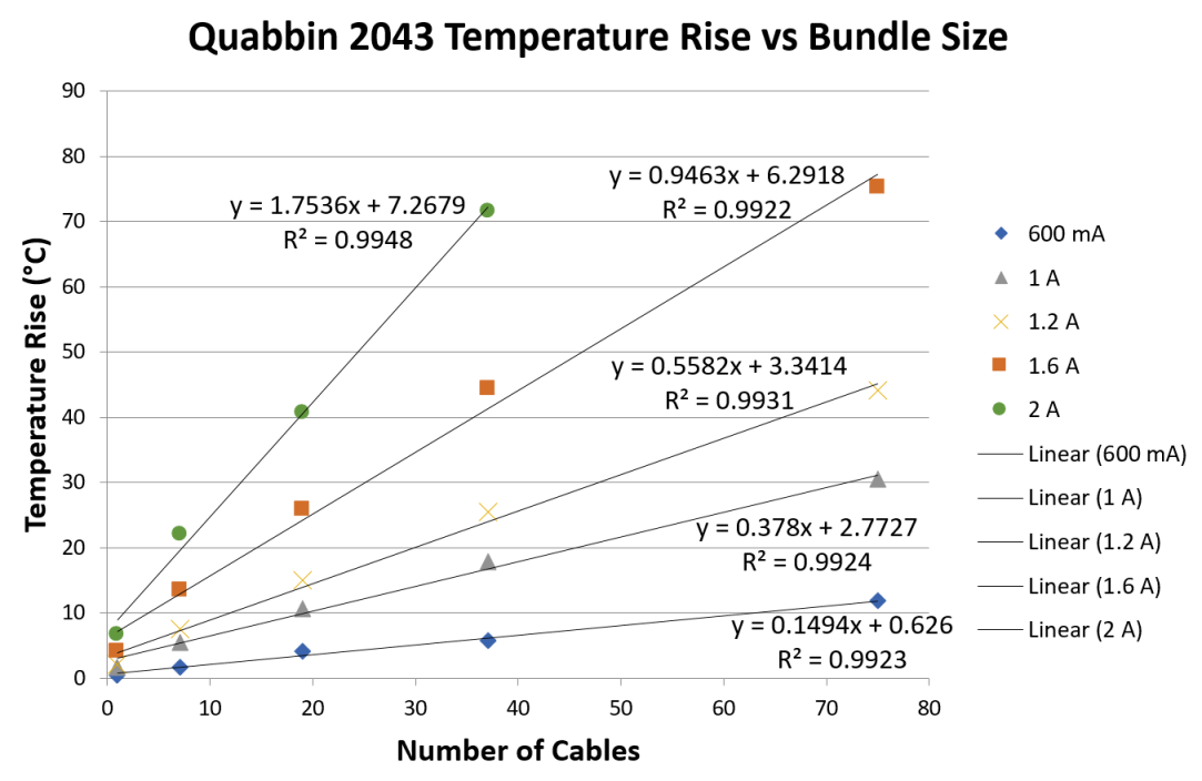
From the data generated by these tests, Quabbin derives trend lines for temperature rise versus number of cables in a bundle at various current levels. From these trend-line equations, the maximum bundle size for a desired maximum temperature rise can be calculated. This is accomplished by choosing the trend-line equation for the required current level, inputting the desired temperature rise as the y-value and solving for the x-value. The x-value is the number of cables in a bundle that will raise the bundle temperature by the amount specified at the given current level.
Based on these calculations, Quabbin can specify the maximum bundle size to ensure temperature rise does not exceed a cable’s temperature rating, as well as the maximum bundle size to limit temperature rise below a desired maximum value.
| Current |
PN 2222 UTP |
PN 2240 F/UTP 28 AWG 75 C rating |
PN 2043 F/UTP 28 AWG 105 C rating |
PN 2049 F/UTP 26 AWG 105 C rating |
| 600 mA | 264 Cables | 404 Cables | 564 Cables | 1191 Cables |
| 1A | 90 Cables | 130 Cables | 217 Cables | 406 Cables |
| 1.2A | 62 Cables | 90 Cables | 146 Cables | 271 Cables |
| 2A | 21 Cables | 26 Cables | 44 Cables | 90 Cables |
| Current |
PN 2222 UTP |
PN 2240 F/UTP 28 AWG 75 C rating |
PN 2043 F/UTP 28 AWG 105 C rating |
PN 2049 F/UTP 26 AWG 105 C rating |
| 600 mA | 71 Cables | 106 Cables | 96 Cables | 204 Cables |
| 1A | 22 Cables | 31 Cables | 32 Cables | 64 Cables |
| 1.2A | 15 Cables | 20 Cables | 20 Cables | 41 Cables |
| 2A | 2 Cables | 2 Cables | 4 Cables | 9 Cables |
Quabbin has also performed testing on cable performance over temperature on several of their constructions. Terminated assemblies are placed inside bundles of cable and a thermocouple is used to monitor the temperature in a cable next to the assembly. Handheld testers are used to measure cable performance at different temperatures and this data is compared to room temperature cable performance. This measurement was performed the Mini-6 unshielded and Mini-6A shielded cables. The results of this measurement are shown below:
From the testing Quabbin has performed there is a clear performance advantage to using a shielded cable vs an unshielded cable, especially when it comes to insertion loss. The shielded Mini-6A cable insertion loss is degraded by about 10% whereas the unshielded Mini-6 cable insertion is degraded by upwards of 30%. The shielding offers some protection from the high loss jacketing materials used in these constructions.
Conclusion
28 AWG and 26 AWG stranded patch cables offer a number of benefits over heavier, thicker gauge cables for PoE implementations. Thin patch cables are more flexible, lighter and take up less space. There are, however, important design considerations that should be taken into account when using thin patch cables for PoE applications. In particular, higher DC resistances generate more heat dissipation and steeper temperature rises in thin cables, necessitating careful consideration of safe amperage levels and bundle sizes that will not exceed cable temperature ratings. Several standards and guidelines offer guidance on these factors.
Quabbin Wire and Cable Co. makes it easy to determine the proper cable configuration for specific applications based on empirical temperature rise test data. Contact Quabbin today to learn more about the optimal DataMax commercial data cable for your application.